An electronic scoreboard is one of the most important gadgets anybody can have during any sports tournament. Old manual scoreboard using conventional methods are very time consuming and Error-prone, hence a computerized scoreboard becomes necessary where the display unit needs to be changed in real-time. This is why in this project, we will be building a Bluetooth controlled wireless scoreboard in which we can change the score on the board just by using an android application. The brain of this project is an Arduino Nano, and for the display part, we will be using a P10 LED matrix to show the score remotely in real-time.
The P10 LED Display Matrix
A P10 LED Matrix Display is the best way available to make a LED advertisement board for outdoor or indoor use. This panel has a total of 512 high brightness LEDs mounted on a plastic housing designed for best display results. It also comes with an IP65 rating for waterproofing making it perfect for outdoor use. With this, you can make a big LED signboard by combining any number of such panels in any row and column structure.

Our module has a size of 32*16, which means that there are 32 LEDs in each row and 16 LEDs in each column. So, there is a total of 512 LEDs present in each led signboard. Other than that, it has an IP65 rating for waterproofing, it can be powered by a single 5V power source, it has a very wide viewing angle, and the brightness can go up to 4500 nits. So, you will be able to see it clearly in brought daylight. Previously we have also used this P10 Display with Arduino to build a simple LED Board.
Pin Description of P10 LED Matrix:
This LED display board uses a 10-pin mail header for input and output connection, in this section, we have described all the necessary pins of this module. Also, you can see there is an external 5V connector in the middle of the module which is used to connect the external power to the board.
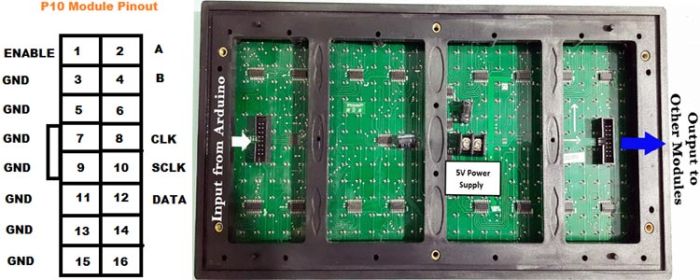
- Enable: This pin is used to control the brightness of the LED panel, by giving a PWM pulse to it.
- A, B: These are called multiplex select pins. They take digital input to select any multiplex rows.
- Shift clock (CLK), Store clock (SCLK), and Data: These are the normal shift register control pins. Here a shift register 74HC595 is used.
Interfacing P10 LED Display Module to Arduino:
Connecting the P10 matrix display module to Arduino is a very simple process, in our circuit, we configured pin 9 of the Arduino as Enable pin, Pin 6 as Pin A, Pin 7 as pin B, Pin 13 is the CLK, Pin 8 is the SCLK, Pin 11 is the DATA, and finally Pin GND is the GND pin for the module and Arduino, a complete table below explain the pin configuration clearly.
Note: Connect the power terminal of the P10 module to an external 5V power source, because 512 LEDs will consume a lot of power. It is recommended to connect a 5V, 3 Amp DC power supply to a single unit of P10 LED module. If you are planning to connect more numbers module, then increase your SMPS capacity accordingly.
Components Required for Arduino Scoreboard
As this is a very simple project, the components requirements are very generic, a list of required components are shown below, you should be able to find all of the listed material in your local hobby store.
- Arduino Nano
- P10 LED matrix display
- Breadboard
- 5V, 3 AMP SMPS
- HC-05 Bluetooth Module
- Connecting Wires
Circuit Diagram for Arduino Scoreboard
The Schematic for the Arduino LED Scoreboard is shown below as this project is very simple, I have used the popular software fritzing to develop the schematic.

The working of the circuit is very simple, we have an Android application and a Bluetooth module, to successfully communicate with the Bluetooth module, you have to pair the HC-05 module with the android application. Once we are connected, we can send the string that we want to display, once the string is sent, Arduino will process the string and convert it to a signal that the internal 74HC595 shift resistor can understand, after the data is sent to the shift resistor, its ready to display.
Arduino Scoreboard Code Explanation
After the successful completion of the hardware setup, now it’s time for the programming of Arduino Nano. The stepwise description of the code is given below. Also, you can get the complete Arduino Scoreboard code at the bottom of this Tutorial.
For More Details: Build an Arduino Scoreboard using Outdoor P10 LED Matrix Display and Update Scores Remotely using Smartphone