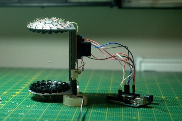
Acoustic levitator from Asier Marzo is a very popular thing here on instructables. I build it, it was working but I noticed couple of issues. For example:
- The 3D printed space between bowls is a bit fragile.
- The levitator can’t stand on its own because of its curvature.
- All the electronics are fragile and a bit ugly.

So I built this case. It does couple of things like:
- Serves as a stand.
- Hides all the electronics.
- Iluminates levitated objects.
- Changes the voltage going into driver which is important when levitating liquids.
- Shows input and output voltage.
If you look at the second image you can notice that many changes have been made to the original model.
Step 1: Parts List
You will need these components:
LM2577 variable step-up converter
2x white LEDs
2x UV LEDs
Acrylic, MDF or other material what are you going to cut it from
IP68 endoscope camera (optional)
endoscope camera holder (optional)
Step 2: Tool List

These tools might be handy:
1) laser cutter (I used GCC SLS 80)
2) soldering iron
3) hot glue gun
4) acumlator drill
5) screwdriver set
6) drill bit set
7) cable stripper
8) multimeter
9) marker
Step 3: Cutting the Case

Why did I choose laser cut case instead of 3D printed one? The answer is simple. It’s faster to make, cheaper, and the final case will be very robust.
The thing to do now is to choose material you’re gonna cut it from. Wood or MDF is elegant and cheap, and acrylic is futuristic and if you add see throught acrylic you’re gonna see all the electronics inside. I chose acrylic.
I designed this case in Corel. If you don’t have acces to a laser cutter (as me) there are many local services, that you can give this file to, and they will cut it to you for affordable price. All needed files are included in this step.
Note: This case was drawn for 3mm thick material. Make sure that you have this thickness.
Step 4: Getting Pieces Together

You have all pieces alreday cut, they all fit, so now you can build the case. Imagine that the case is a prism and the C shape is base. Now with a little 3D imagination sense I’m sure that you can build it.
Step 5: Adding Levitator Core
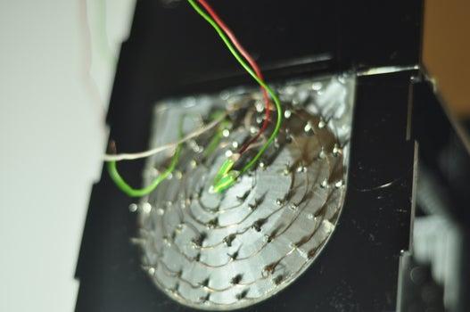
Now if you have built the basic case shape, you can add the levitator core. The case is designed that way, that it fits the curvature of levitator. Just insert the levitator between two holes of case, and glue it in place.
Step 6: Adding Electronics

The levitator is glued in, so now it’s the right time to connect all necessary electronics. The best option is to glue driver in the middle part, so wires from top and bottom bowls don’t have to be so long and you have to put bunch of other stuff in the bottom part of the case. Wires from driver will then go to arduino nano, which will be in bottom part of case. Very important thing to do is to add a jumper between D10 and D11 of arduino nano.
The DC barrel connector will be also in the middle part. At first, energy from it will go right into driver, but later, it will go to li-ion battery charger module and the driver will be powered from li-ion battery. That means that levitator will work even away from outlet.
I also added a switch at the front control panel. One pin of switch is connected to + of DC barrel and the other to 12V input of driver. This will be necessary when it will be powered from li-ion battery.
Step 7: Adding Ilumination

In general the particles that can levitate are small. And small things are hard too see. So I think that LED ilumination is a good idea. I just drilled two 3mm holes in plastic at the top and bottom of levitator. Then I glued both LEDs in place and connected them to 3.3V output of arduino nano.
One cool idea is to paint particless that’ll levitate with UV highlighter and glue UV LEDs instead of the classic ones. I added both normal and UV ilumination. I also added switch, so I can switch between UV and normal. The best place to place the UV LEDs is in the gap between control panel and the rest of the case.
If you want just normal ilumination, just connect both white LEDs to GND and 3.3V outputs of arduino nano. If you want both normal and UV, follow included scheme. More info about mounting UV LEDs is in step 10.
I uploaded some pictures for comparison of UV and LED. All these pictures were shooted at absolute darkness (no ambient light). As you can see, normal LEDs iluminate the whole device, while UV LEDs highlight the particle itself (and that’s super cool at night).
Step 8: Electronics – Volume II
At first, you need to desolder the original 10K trimmer from LM2577 and replace it with precise 10K potentiometer. Also adding a potentiometer knob is a good idea.
Connect + pole of the DC barrel to IN+ of LM2577 and connect – from the DC barrel to IN- of LM2577. Then connect OUT+ and OUT- from LM2577 to 12V and GND of L298N.
Step 9: Add Control Panel
When there are so many electronics to control in this device, I think that adding a control panel is a good thing. These are the things that you can control from this panel:
1) turn the device ON or OF
2) switch between white LED and UV LED ilumination
3) control and check voltage going into driver (this is important when levitated object are not symetric and stable)
So, I just drilled three holes for two switches and for potentiometer and glued LM2577 in place. Hole for voltage display is laser cut. Then I glued UV LEDs. It’s important to aim UV LEDs precisely (It’s a beam more that a light).
For More Details: Acoustic Levitator Case