Wireless power transfer systems are well on their way to replacing conventional wired charging. Ranging from tiny biomedical implants all the way to wirelessly recharging huge electric vehicles. An integral part of the research on wireless power is minimizing the magnetic field density. The International Commission on Non-Ionizing Radiation Protection (ICNIRP) provides scientific advice and guidance on the health and environmental effects of non-ionizing radiation (NIR) to protect people and the environment from detrimental NIR exposure. NIR refers to electromagnetic radiation such as ultraviolet, light, infrared, and radiowaves, and mechanical waves such as infra- and ultrasound. Wireless charging systems produce alternating magnetic fields which could be harmful for human beings and animals present in the vicinity. To be able to detect these fields and minimize them in a real-world test setup, a magnetic field measuring device like the Aaronia SPECTRAN NF-5035 Spectral Analyzer are required. These devices usually cost upwards of $2000 and are bulky and may not be able to reach narrow spaces where the field needs to be measured. Additionally, these devices usually have more features than required for simple field measurement in wireless power transfer systems. Hence, developing a smaller, cheaper version of the field measuring devices would be of great value.
The current project involves the design of a PCB for magnetic field sensing and also the design of an additional device that can process the sensed magnetic field values and display them on an OLED or LCD display.
Step 1: Requirements
The device has the following requirements:
- Measure alternating magnetic fields in the range of 10 – 300 kHz
- Measure fields accurately up to 50 uT (Safety limit set by ICNIRP is 27 uT)
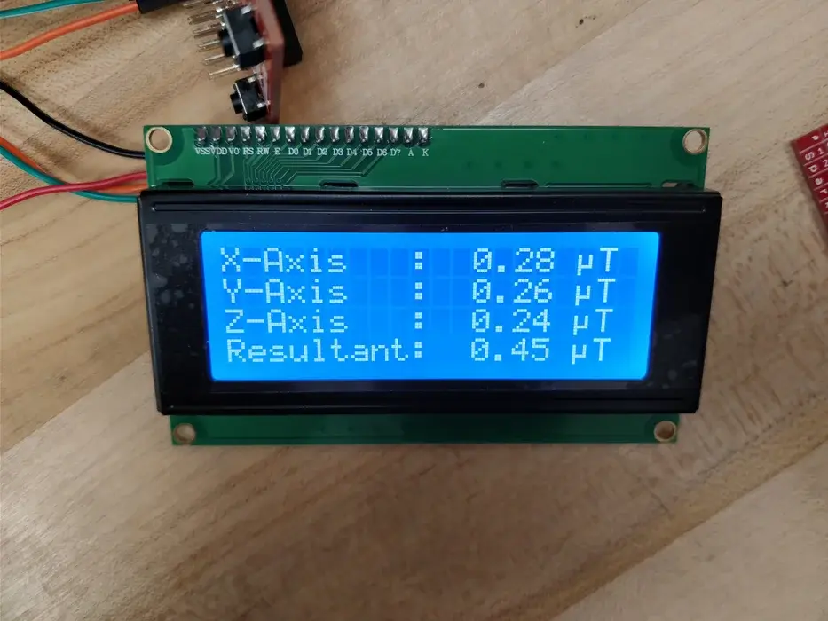
- Measure fields in all three axes and get their resultant to find the actual field at a given point
- Display the magnetic field on a handheld meter
- Display a warning indicator when the field goes above the standards set by the ICNIRP
- Include battery operation so that the device is truly portable
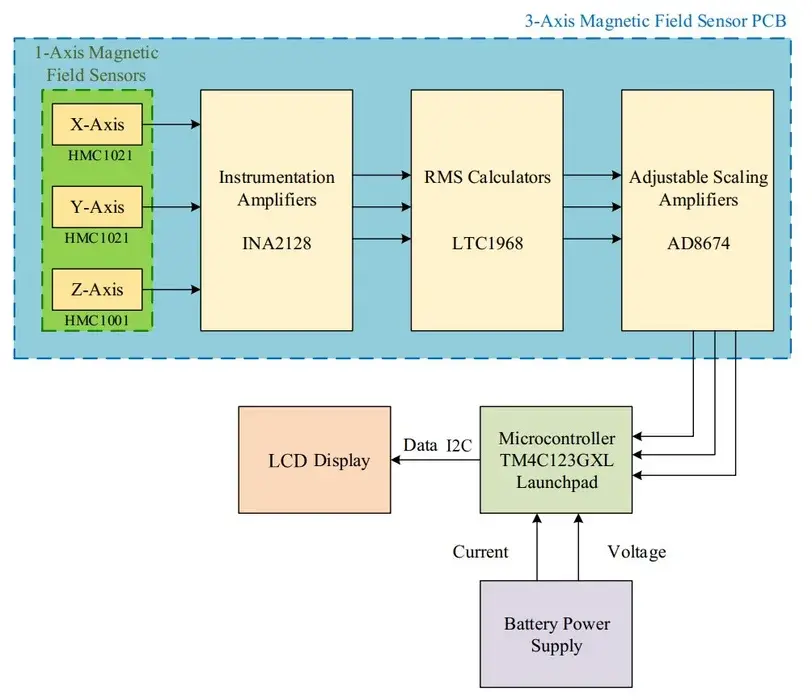
Step 2: System Overview
Step 3: Choosing Components
This step is probably the most time taking step, requiring considerable patience to pick out the right components for this project. As with most other electronics projects, choosing components requires careful examination of datasheets to make sure all the components are compatible with each other and work in the desired range of all the operating parameters – in this particular case, magnetic fields, frequencies, voltages etc.
The major components chosen for the magnetic field sensor PCB are available in the attached excel sheet. The components used for the handheld device are as follows:
- Tiva C TM4C123GXL microcontroller
- SunFounder I2C Serial 20×4 LCD display
- Cyclewet 3.3V-5V 4 channel logic level converter bidirectional shifter module
- Push button switch
- 2 position toggle switch
- 18650 Li-ion 3.7V cell
- Adafruit PowerBoost 500 Charger
- Printed circuit boards (SparkFun snappable)
- Standoffs
- Connecting wires
- Header pins
The equipment required for this project are as follows:
- Soldering device and some solder wire
- Drill
- Wire cutter
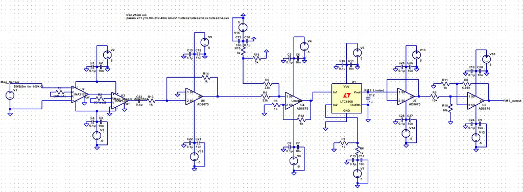
Step 4: Circuit Design and Simulation
{“context”:{“location”:{“href”:”https://www.instructables.com/editInstructable/edit/EMGJXE1JFUAH4P7″,”origin”:”https://www.instructables.com”,”protocol”:”https:”,”host”:”www.instructables.com”,”hostname”:”www.instructables.com”,”port”:””,”pathname”:”/editInstructable/edit/EMGJXE1JFUAH4P7″,”search”:””,”hash”:””},”jQuery110209470777035602441″:1,”b”:{“jQuery110209470777035602441″:20},”h”:{}},”selector”:”#editor-Object-28″}
Step 5: Designing the PCB
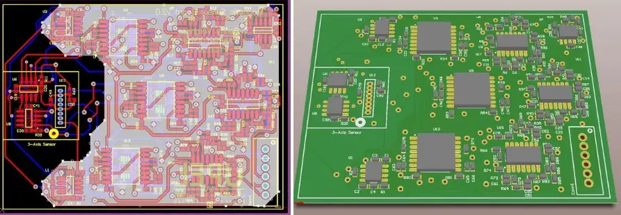
Once the circuit operation is verified in LTSpice, a PCB is designed. Copper planes are designed in a way that they don’t interfere with the working of the magnetic field sensors. The highlighted grey region in the PCB layout diagram shows the copper planes on the PCB. On the right, a 3D view of the designed PCB is also shown.
Step 6: Setting Up the Microcontroller
The microcontroller chosen for this project is the Tiva C TM4C123GXL. The code is written in Energia in order to make use of existing LCD libraries for the Arduino family of microcontrollers. Consequently, the code developed for this project can also be used with an Arduino microcontroller instead of the Tiva C (provided you use the right pin assignments and modify the code accordingly).
Step 7: Getting the Display to Work
The display and the micro-controller are interfaced via I2C communication which only requires two wires other than the a +5V supply and ground. The LCD code snippets available for the Arduino family of microcontrollers (LiquidCrystal libraries) have been ported and used in Energia. The code is given in the attached LCDTest1.ino file.
Some helpful tips for the display can be found in the following video:
Step 8: 3D Printing
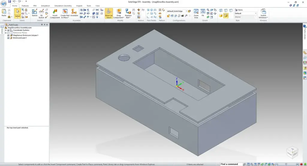
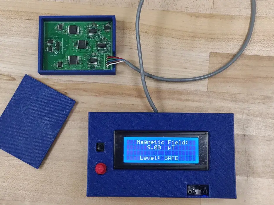
An enclosure box for the handheld device is designed as shown in the image above. The box helps keep the boards in place and the wires undisturbed. The box is designed to have two cutouts for the wires to go through, one cutout for the battery indicator LEDs, and one each for the toggle switch and push button switch. The necessary files are attached.
Step 9: Interfacing All the Components
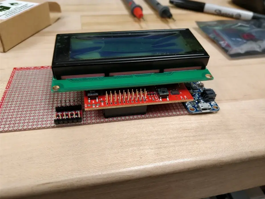
Measure the dimensions of all available components and lay them out using a graphical tool such as Microsoft Visio. Once the layout of the all the components is planned, it is a good idea to try and place them in their positions to get a feel of the final product. It is recommended that the connections be tested after each new component is added to the device. An overview of the interfacing process is shown in the images above. The 3D printed box gives a clean look to the device and also protects the electronics inside.
Step 10: Device Testing and Demonstration
The embedded video shows the device operation. The toggle switch turns on the device and the push button can be used to shuffle through the two display modes.
Source: 3-Axis Magnetic Field Sensor